Innovation History

PetersInvent two generations of inventions

Our passion is to find solutions

Since 1960 P.J. Peters has developed several inventions in different areas. In 1982, P.J. Peters and MLJP Peters started their collaboration in invention development. PetersInvent is only concerned with product improvement and innovation. PetersInvent is not a producer or manufacturer.

Development of a new Hydraulic Coupling

From 1960 to 1962, P.J. Peters worked on the development of a new hydraulic coupling. Change: The possibility to reach the highest torque in the drive shaft by means of hydraulics. On 30 May 1962, patent applications were submitted in:

Switzerland, no. 6735/62, 22-09-’62
Germany, no. P 30 215 XII/47h, 16-10-’62
France, no. 912 453, 24-09-’62
England, no. 36 225 and 03-08-’62
USA, no. 214 682.

The first patent 19-08-1963 was registered in France under number 1 338 617. Because of the high cost of patent application and prototype construction, this project had to be stopped halfway.

Info Patents
Special Exposure Meter for a Hasselblatt Camera

From 1960 to 1961, P.J. Peters worked in Switzerland at Kern AG in Aarau. In Switzerland, they worked in a team to develop a special exposure meter for a Hasselblatt camera. This camera was sent into space with a rocket to take close-up images of the moon, which did not yet exist at that time. Nobody knew much about the lighting conditions in space. It was therefore necessary to develop an exposure meter with a very wide range. The exposure meter was meant to control the diaphragm by means of a mechanical coupling. When P.J. Peters was employed, they had already partly finished building the exposure meter. According to P.J. Peters, it was too susceptible to failure and had too many parts. P.J. Peters largely revised the whole design, which was a success.

The Ranger program was a series of unmanned space missions by the United States in the 1960s whose objective was to obtain the first close-up images of the surface of the Moon.

Improvements Photo Cameras

From 1963 to 1965, P.J. Peters repaired cameras for AGFA. He did this in the evenings, after his work at the Catholic University of Nijmegen. Many cameras suffered from the same defects. On those points P.J. Peters has made improvements, which were subsequently incorporated in the production line by AGFA.

In a later period P.J. Peters also repaired other brands of photo cameras.

Inventions & Developments
Inventions & Developments in paid employment

Between 1963 and 1968, P.J. Peters was employed by the Catholic University of St Radboud in Nijmegen, as an instrument maker. During this period he was able to make several new successful developments and inventions, which were later taken into production.

  • An improved and more compact heart-lung machine.
    After changing and improving the American heart-lung machine, it was only one third of the original size.
  • New developments (in a team) in renal dialysis equipment.
  • New developments in eye measurement equipment.
  • New developments in peristaltic pumps.
  • The peristaltic pumps were reduced in size and modernised.
  • New developments in shutters for electron microscopes. Because of this invention, razor sharp photos could be made that were no longer deformed.
  • New invention: the clip or clamp made from a spring steel wire, which closes in parallel. The clamp was used to securely seal soft silicone hoses.
Proti Micro Reader
Gold Medal at the 18th INVENTOR SALON at Brussels, 21 – 30 March 1969, with the PROTI MICRO READER,
inventor P.J. Peters

In 1965 there were quite a few institutions that had problems with projecting and quick-searching information on microfilm / microfiche.

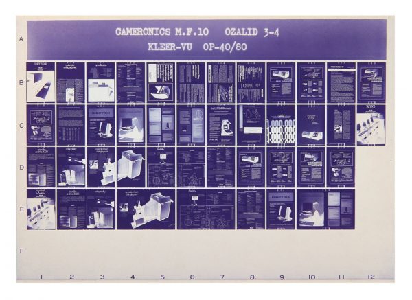
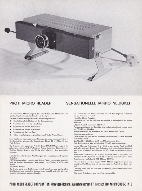
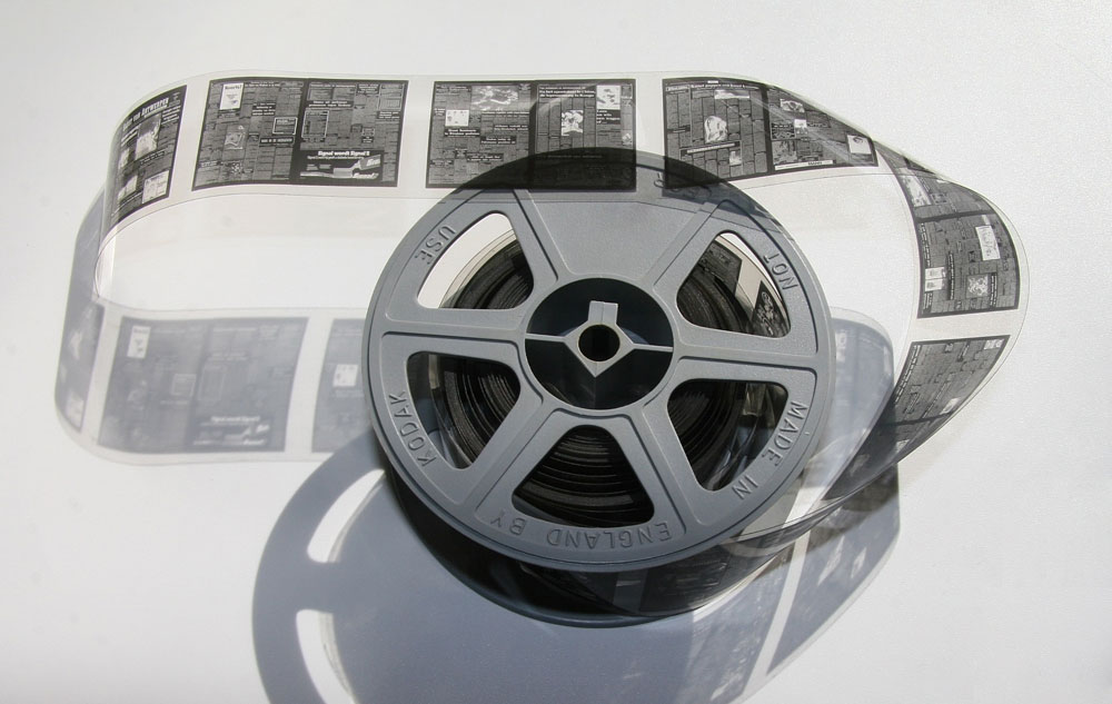
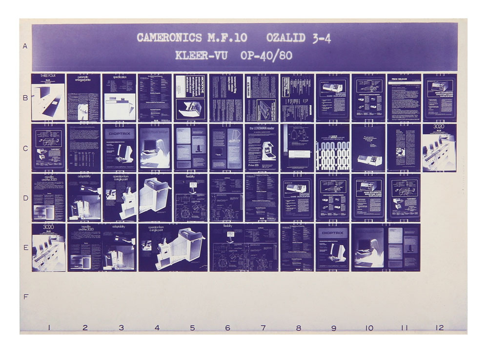
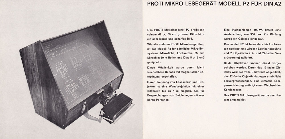
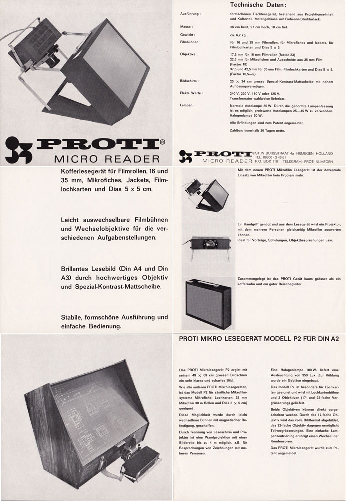
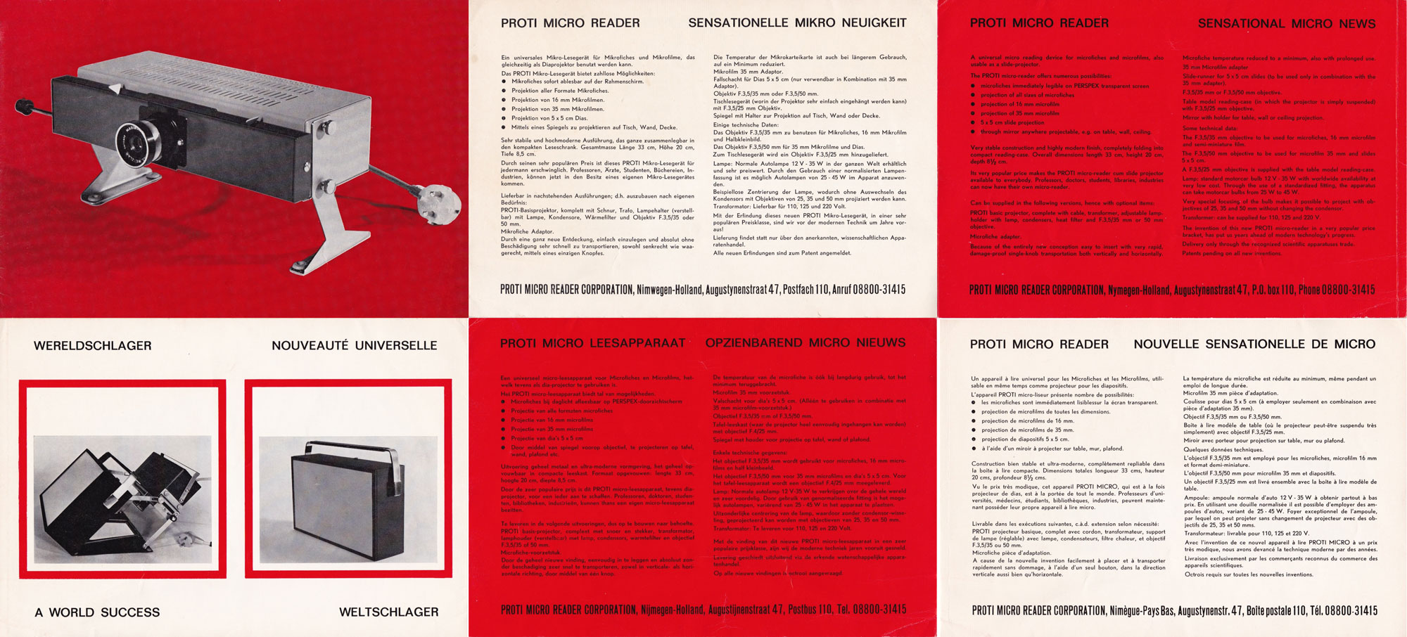
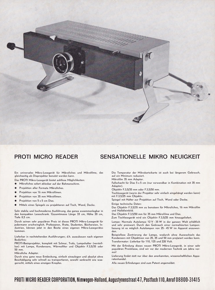
A microfiche is a card made of transparent film used to store printed information in miniaturized form. Each microfiche can accommodate from 48 pages to as much as 152 pages of A4 size. To read the card, a user places it under the lens of a reader machine, which magnifies it greatly. The thinness and small size of the film enables it to be stored very easily and efficiently, allowing libraries, museums and businesses to increase their resource collections without the need for additional storage space.

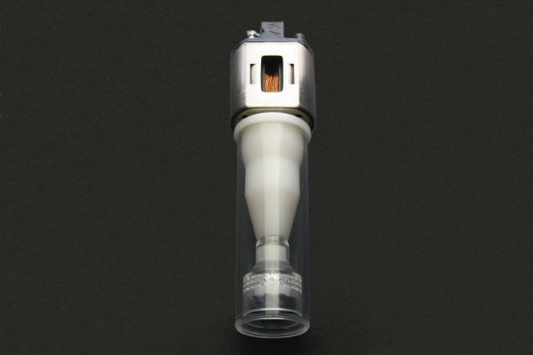
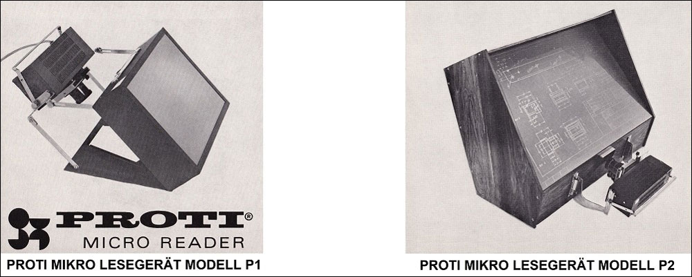
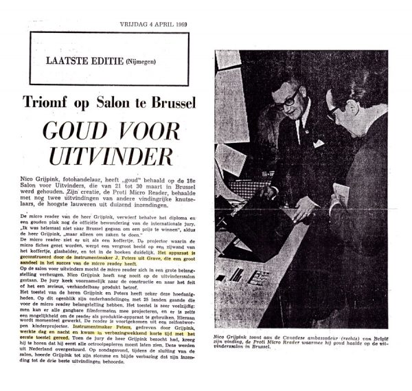
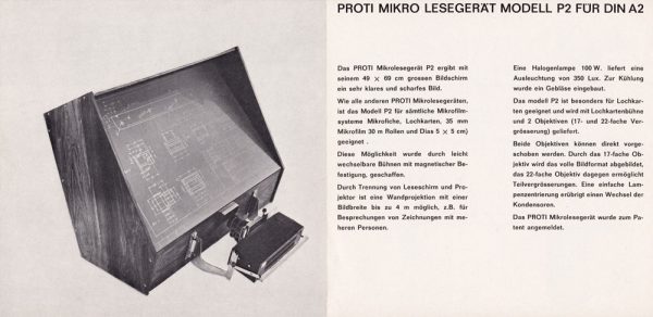
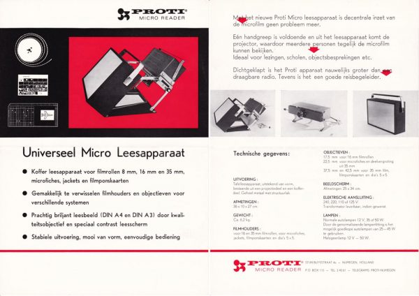
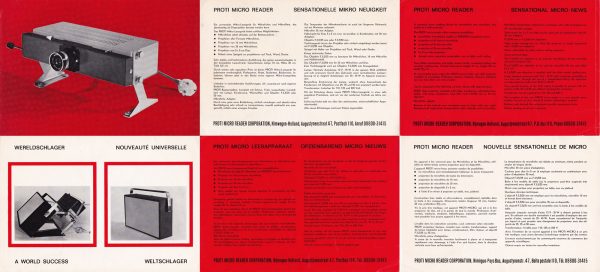
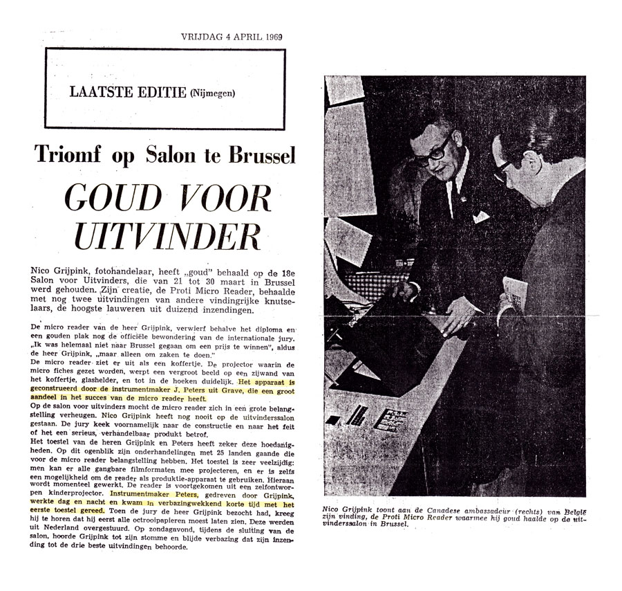
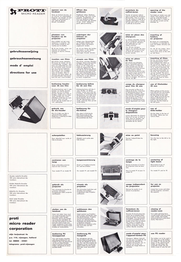
At that time, P.J. Peters was working as freelance photo camera repair technicion for a photographer who had a camera shop in Nijmegen. The photographer was approached by the university, they were looking for a user-friendly and affordable system to read the information on microfilm. From 1966 to 1968 P.J. Peters developed the Proti Micro Reader.

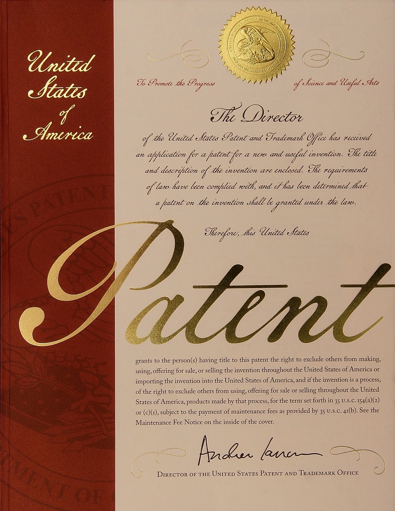
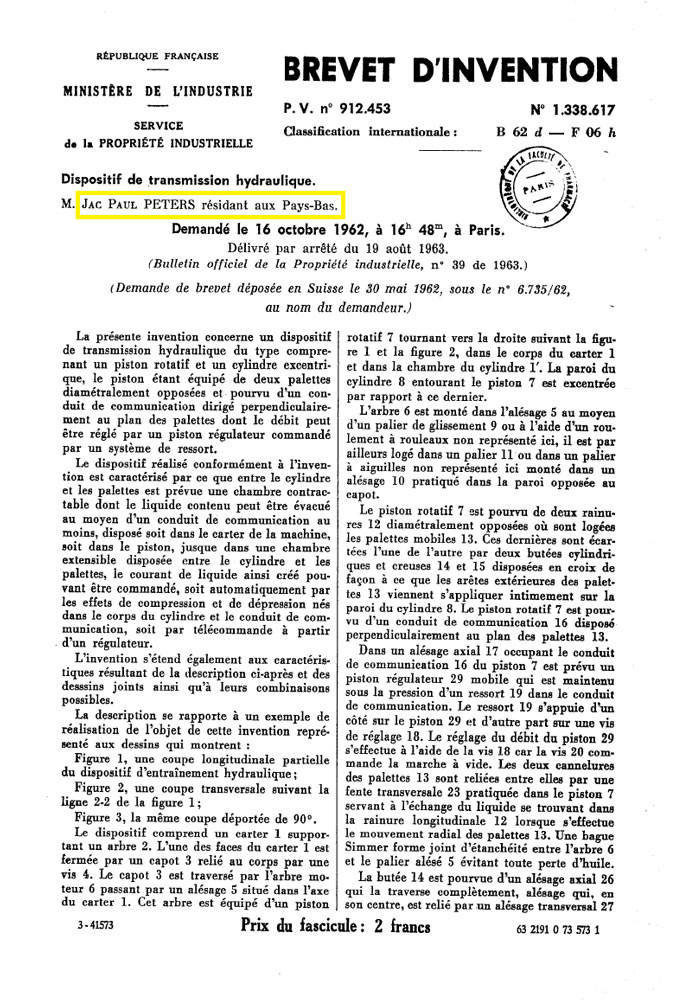
The first patent 6712324 filed on September 8, 1967 Inquiry number: NL19670012324, inventor P.J. Peters. Unfortunately the photographer used his own name as inventor when he made the patent application.

Other countries where a patent was requested are France, Germany, Switzerland, Belgium.

At that time, there were negotiations with 25 countries that had considerable interest in the Micro Reader. Later many companies, institutions, hospitals and libraries from around the world started to use the Micro Reader.

There was a lot of interest from companies such as Kodak, AGFA, 3M COMPAGNY and Océ van der Grinten who all wanted to take over this invention. Even now, so many years later, companies are still selling these Micro Readers.

Info Patents
Transport system for film projectors

In 1976, P.J. Peters invented a new transport system for super 8 and standard 8 film projectors. This made it possible to play images back and forth at variable speed and could be operated manually and with infrared. The German patent was filed on 25-08-1977 and was granted on 31-05-1979 under number 27 38 276, inventor Peters, Paulus Jacobus. Requested by Robert Bosch GmbH, 7000 Stuttgart.

Info Patents
Fast Rewind and Fast-Forward with an Anti-Break System

In 1978, P.J. Peters came up with new invention in relation to film projectors: the possibility to fast rewind and fast-forward a film with an anti-break system built in. Due to the rise of the VHS, this system was not taken into production.

Super 8 Widescreen Projector and Film Camera

In 1987, P.J. Peters invented the first Super 8 widescreen projector and film camera. The existing film camera and projector were modified by P.J. Peters to record and play movies on widescreen (cinema) format. (Article in Smalfilmen Als Hobby, 07-01-1987).

Breakthrough stagnating Cancer Research in the late 70s with the Micro Ultra Centrifuge

During the 1970s cancer researchers were focused upon finding a solution to the issues surrounding the separation of red and white blood cells. At the time, available procedures couldn’t keep the cells separated long enough for proper research as automatic analyses were time-consuming.

Approached by academics at Radboud Hospital Nijmegen, P.J. Peters developed the Micro Ultra Centrifuge late 70s. Operating max. at 6.000 rpm, the innovative design of the Micro Ultra Centrifuge made research on individual blood cells possible for the first time in history a major breakthrough in cancer research. See page 2 PDF of the article: A New Disaggregation Device 1984.

In an act of true altruism, when failures to uphold agreements and rights arose between the stakeholders, P.J. Peters, realising the importance of the Micro Ultra Centrifuge for mankind, decided to donate his innovation to the Wilhelmina Cancer Foundation in the Netherlands.

More information see English or Dutch text.

A New Disaggregation Device For Cytology Specimens
Introduction first development Flow Meter

In 1978, P.J. Peters came up with the idea of developing an accurate fuel flow meter for cars. This innovation was prompted by the oil crisis and ‘car-free Sundays’ in the Netherlands and Belgium from November 1973 to January 1974.

From 1978 to 1979, P.J. Peters invented his first working Flow Meter.
At the end of 1997, a prototype flow meter was developed to accurately indicate the fuel consumption of vehicles every second. This flow meter was primarily intended to register the gasoline consumption in cars. By directly confronting the diver with their driving style, they are able to adjust their driving style to their gasoline consumption. This allows cars and lorries to become more than 12% more fuel efficient. Drivers will immediately see when they are driving most efficiently by applying more or less throttle or changing gears at the right time. All fuel first flows through the flow meter. The mechanically constructed flow meter continuously measures the fuel consumption. It cannot be cheated with.

Whether it is cold or hot, driving uphill or downhill, short or long drives, the actual fuel consumption is continuously recorded by the flow meter.

Due to the light construction of the rotor 0.004 grams, which has a peak frequency of maximum 36.900 rotations per minute at 2 L/min. the fluid can be measured and dosed very accurately. In the housing, the fluid (liquid or gas) is swirled. The rotor in the housing is rotated by the swirled fluid. By counting the number of rotations, a reading can be obtained, which is representative of the amount of fluid that flowed through the meter.

This prototype was not yet ready for production. with this prototype it was possible to test in cars. Making a prototype ready for production, suitable for mass production is a completely different story. This requires specialist knowledge and innovative adjustments to achieve this in terms of production technology. Newspaper article De Gelderlander March 3, 1983; This will be a gold mine

Research has shown that the flow meter has many more useful applications. It consists of plastic parts, with some electronics for detection of the rotor.

The first three generations of rotor Flow Meters are still being sold today, after more than 35 years, for different applications around the world.

First generation Flow Meter

In 1978, P.J. Peters develop the first generation Flow Meter.

The Dutch patent was filed on 21-12-1979 under No. 7909271, and was granted on 10-06-1980, patent no. NL 8003374.
The European patent was granted on 09-04-1986, Publication No. 0 031 629 A1
The U.S. Patent was assigned on 02-08-1983, No. 4,395,919. Inventor P.J. Peters

The flat rotor of the 1st generation flow meter shows a “lagging effect”. Later, a rotor was developed with three straight blades. The first rotor blade now has three openings instead of one.
These openings cause an interruption of the infrared signal while rotating, generating three pulses per rotation. The new construction of the rotor weighs 0.004 grams. Whith a peak frequency of 24.000 rotations at 2 L/min per minute. the fluid can be measured and dosed very accurately.

Second generation Flow Meter

In 1984, P.J. Peters develop the second generation Flow Meter.
The big difference between the 1st generation and 2nd generation flow meter is the design of the rotor blades and housing of the electronics. The three blades of the 2nd generation rotor are curved, allowing for a more effective contact with the fluid. The housing for the photo cells is constructed differently than in the first generation flow meter. Due to the super-light construction of the rotor 0.005 gram, which has a peak frequency of maximum 81.800 rotations per minute at 4 L/min. The fluid can be measured and dosed very accurately.

First, the Swiss patent was requested on 12-12-1985. The patent was granted on 15-02-1989, No. CH 669 039 A5.
The European patent was granted on 15-07-1987, Publication No. 0 228 577 A1
The U.S. patent was granted on 29-03-1988, No. 4,733,570. Inventor P.J. Peters

Third generation Flow Meter

In 1990, P.J. Peters develop the third generation Flow Meter.
On 16-11-1990 a European patent was filed. The European patent was granted on 29-6-1994, Publication No. 0 485 684 A1. Inventor P.J. Peters.

The first and second generation flow meters have a housing, rotor and a worm. Those three components form the heart of the flow meter.
The housing contains a narrow bridge with a bearing hole in the middle. First, the rotor is positioned in the bearing hole of the housing part. At the end of the worm there is another bearing hole. Finally the worm is carefully pushed into the housing part. At the same time, the rotor shaft should be positioned in the bearing hole of the worm. The assembly is a very precise job. In the third generation flow meter, the housing and flow guides form one piece. The flow guides are not spiral shaped like in the first and second generation flow meters, but straight with an angled tip. This generation also requires the rotor to be mounted manually. The rotor and the shafts are inserted in a bearing hole of the housing and into a bearing hole of the stop plate. The bearing hole is in the middle of the stop plate. The round stop plate that is clamped into the housing of the worm will force the fluid to flow into the flow guides at the last moment, causing the fluid to swirl.

For the first time, we used a PCB on which the photocells and other components were automatically mounted with a pick-and-place system.
The assembly of the rotor is still a precise and time-consuming job in the third generation flow meter.
The first three generations of flow meters with a rotor are not suitable for mass production, as their difficult assembly must be done manually.

Development Rotors

Development different versions rotors in the period between 1978 to 1990.

Fourth generation Flow Meter

Although the previous three generation rotor-based flow meters function well in their respective deployment areas, there are a number of limitations.
Due to these restrictions, we are developing a fourth generation flow meter. In order to improve the limitations, we have developed a completely new construction based on a ball.

Each time we face the challenge of improving our products by designing new constructions that offer more benefits. Another important goal we set ourselves is that the new developments must be patentable. Our strength is that we build the prototypes ourselves, as they would be made using mould technology.
Just as every car manufacturer introduces new innovations to the market every year, we are also constantly working on new developments, not just regarding flow meters but in a number of areas. We come up with solutions and our strength is the innovative design of new applications. New developments are essential to humanity and our future and will never stop.

Flowmeters based on a rotor are highly sensitive to dirt particles. The slightest contamination and air bubbles can cause the relatively light rotor to get stuck. As a result, flow meters based on a rotor can only be used for very clean liquids. This is a huge limitation for the various application areas for liquids where flow meters are desirable.

Good filter systems are expensive and need to be replaced regularly. Another drawback is that filter systems increase the resistance in a conduit. As the dirt in a filter accumulates, the resistance in the pipe also increases. Therefore, filters must be regularly replaced or cleaned, which is costly. The system must be opened to replace the filter, which is not conducive to certain processes. As a consequence, the production process will temporarily come to a standstill.

Another major disadvantage of flow meters with a rotor is that the rotor must be manually assembled. The thin shaft of the rotor must be mounted very carefully in the small holes of the bearings, which can only be done manually. When it comes to producing large numbers, this is time-consuming and expensive work. Sterile assembly of the rotor and the rest of the components, e.g. for the pharmaceutical industry, is not possible in automated production.

Companies that do not develop further come to a standstill and will not survive in this new competitive society. Our strongest side, through years of experience, is that we are able to improve and adapt flow meters for specific purposes.

First version Fourth generation Flow Meter based on a ball

NL1013231 (C2) 2001-04-09 Inventor MLJP Peters

The fourth generation flow meter is constructed in a completely different way. We succeeded in constructing a very accurate flow meter that is no longer susceptible to contaminated liquids. This greatly increases the applicability of the flow meter.

Due to this new construction, the assembly time is considerably shortened to just a few seconds. Because of its simplicity, the assembly can be fully automated to produce large numbers.

The rotor has been replaced by a ball. The first test results are amazing, as seen on knop at 3.40 minutes in which a pipeline full of sand flows through the flow meter smoothly and completely.

When the sand has passed the flow meter, the ball continues to rotate without problems. This is possible due to the new ball-based construction. This test is heavily exaggerated, but the results are amazing.

After some time I came up with new ideas to improve the first version of the fourth generation flow meter. This resulted in the second patent application of the fourth generation: a new constructed ball-based flow meter.

Technical developments will never stop. This also applies to flow meters. Inventors will always strive for continuous innovation. When the product has been brought to market, new ideas will be developed. The possibilities of the fourth generation flow meter are an example of this.

Info Patents
Second version Fourth generation Flow Meter based on a ball
Silver medal at the International Trade Fair iENA at Nürenberg, 2 November 2013, with the Highly Accurte,
Low Cost, Disposable Flow Meter.
Inventor MLJP Peters
Info Patents
Third version Fourth generation Flow Meter based on a ball

WO2015065187 (A1) 2015-05-07 Inventor MLJP Peters

Uploading a video of this flow meter on knop suddenly generated a lot of interest in this innovation. Because of this video, I received a lot of response from interested companies around the world. Companies I could never have reached otherwise. Judging by the many applications, there appears to be a high demand for a flow meter with these renewed properties.

The many comments on YouTube prompted me to develop and improve the second version by making new adjustments. One of the big differences is that the 3rd version flow meter does not have a cage construction.

Info Patents
Advantages 4th generation Flow Meter
  • Due to its new construction, this flow meter is not sensitive to contaminated liquids. The gap between the blades determines the size of the dirt particles that are allowed to pass.
  • A distinctive feature of the measuring instrument is its high measuring accuracy in a variable range between 1 and 18 lmin with a less than 2% deviation. Repeat accuracy is less than 0.5% in this area.
  • This construction allows the liquid or the gas to flow in two directions without problems. The infrared measurement is in one direction, the direction in which the fluid is swirled by the worm and the ball is rotated by the swirl.
  • The flow meter can be mounted in any desired position. It is not sensitive to air bubbles in the conduit. Best position is vertical, the flow going upwards. This applies to all flow meters. Gravity causes the air bubbles to be naturally carried along with the flow.
  • The new construction allows for quick and easy assembly. The assembly can be done automatically. Due to this new development, the flow meter is very suitable as a mass-produced item for a variety of applications.
  • Because of this construction it should be possible to dose thicker fluids, like paint or gear oil SAE150 with Viscosity 43.000 CentiStokes. The temperature of the oil and the throughput speed are important.
  • Due to the construction of this flow meter, it is possible to adapt the specific gravity of the ball (plastic/metal) to the different types of fluids. The weight of the ball can be adjusted to the fluid viscosity for the best results.
  • By installing a metal housing, this flow meter can operate at a pressure of 100 bar or more.
  • Because of the open worm and open outlet, there is less pressure drop compared to other flow meters. The fluid flow is minimally impeded at the outlet of the flow meter.
  • Thanks to its advanced construction, the flow meter is easy to clean. If the flow meter is blocked by dirt particles that are too large for the flow meter to handle, the dirt/blockage can easily be removed by letting clean liquid flow through the flow meter in the opposite direction.
  • The flow meter is small and compact, making it easy to install.
  • The electronics that detect the bullet can be converted into three different systems: Infrared System, Infrared Reflection System, Inductive Proximity Sensor. This makes the flow meter even more widely applicable. The Infrared System is the most common and also the most inexpensive system.
  • Because of the infrared reflection system, the flow meter can be completely immersed in the liquid. Together with a metal housing, the flow meter is also suitable for explosive fluids.
  • With the Inductive Proximity Sensor, a metal ball can be detected in non-transparent liquids, such as paint, milk, oil or high viscosity liquids.
  • This latest ball-based flow meter is very suitable for pressurized liquids and liquids with gas bubbles, such as carbon dioxide in beer. This is a problem with plastic flow meters equipped with a rotor: whenever a gas bubble passes the rotor, due to the pressure in the pipeline, shortly rotates the rotor so fast that the shafts of the rotor may fuse into the bearings. This means that flow  meters with a rotor are less suitable for systems like this.
Advantages 360° click system electronic housing
  • The plastic housing for the electronics can be placed in desired position as a 360º click system, unlike the cumbersome assembly between the pipes, as is required for flow meters with a fixed electronic connection.
  • The electronics housing can be turned 360º around the flow meter while the latter is in operation. The plug can be easily removed and fits in only one way.
  • The electronics housing can be clicked on or removed from the flow meter while it is running. Due to this construction there is no contact with the liquid, allowing these operations to be done in a sterile way.
  • The rotation of the ball is visible through the opening of the electronics housing, making it possible to easily find the cause of a malfunction.
  • For disposable systems in which only the flow meter is replaced, the electronics can be used over and over again. Because the electronics and flow meter are independent components, the flow meter and electronics are available separately. Reuse of the electronics is not only cost-effective but also environmentally friendly.
PetersInvent 4 Generaties Flow Meters
Developed by PJ Peters and MLJP Peters
To Store Leftover Paint for many years
Inventor MLJP Peters

Prevent Paint Pollution.

An innovation suitable to hermetically seal viscous and water-like liquids.

This innovation prevents paint from drying out by hermetically sealing it from the outside air. As a result, once the can has been opened, the paint can be stored for a very long time without loss of quality and without the paint drying through evaporation.

The way in which paint dries is called ‘physical drying’, which means that oxygen particles transport the volatile organic compounds in the paint outwards. The volatiles in this case are solvents. As the solvents evaporates, the paint thickens and a film forms on top of the drying paint. Paint drying out is usually caused by a poorly closing/ damaged metal lid or too much air trapped in the can.

The construction of the innovation/ seal will prevent the paint from drying out for at least two years, which makes it possible to use the paint to the last drop. How much paint is left in the can does not matter, because the seal is always directly on the surface of the paint. This innovation makes the original metal cover redundant. The seal can be removed and replaced quickly and easily.

Long-term testing using only the seal without the original metal lid has shown that ¼ liter of “Acrylic Lacquer” stays liquid for up to 6 years.

The innovation was initially only developed as a hermetic seal for viscous liquids such as paint. Further development made the seal suitable for hermetically sealing water-like liquids such as drinking water and fluid foods. The seal will also be very useful for many other liquids and applications such as long-term transport.

A second favorable favourable feature of this innovation is that it prevents outside contamination. It is sustainably developed and reusable time and time again. The seal can be produced in almost any shape.

The idea of the seal came into being after hearing about the enormous amount of paint waste that is still burned or processed annually. Any contribution to reducing this enormous amount of toxic waste will help the environment. Another argument to support this innovation is that no one wants to throw away half a can of expensive paint solely because it has dried out. This causes a huge waste of valuable raw materials worldwide every year.

The seal is inexpensive to produce and therefore affordable for every user.

Unfortunately, details of the composition cannot be revealed because the product is not yet protected. This knowledge is registered. Where new developments can be registered safely. This legally recognized system can be used as legal evidence.

PetersInvent is only concerned with product improvement and innovation. PetersInvent is not a producer or manufacturer.