Innovation History

PetersInvent two generations of inventions

Our passion is to find solutions

Gedreven door innovatie, geworteld in ervaring, PetersInvent bouwt voort op een familietraditie die begon in 1960. Wat in 1982 startte als een nauwe samenwerking tussen P.J. Peters en M.L.J.P. Peters, is uitgegroeid tot een onderneming waar passie voor techniek en doorzettingsvermogen centraal staan.
Wat begon als specialistische familie-expertise, is onder leiding van M.L.J.P. Peters geperfectioneerd tot een reeks revolutionaire flowmeters. Wij maken het onmogelijke meetbaar door generaties aan kennis te vertalen naar de technologie van morgen.

3 baanbrekende generaties in flowmeter-technologie

3 revolutionair nieuw ontwikkelde flowmeters

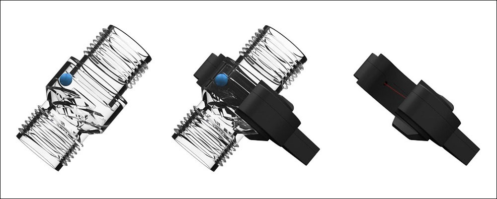
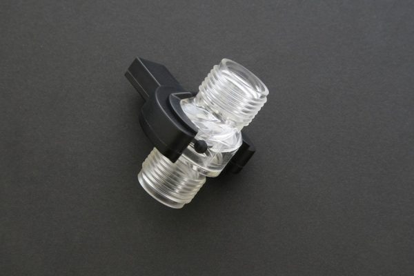
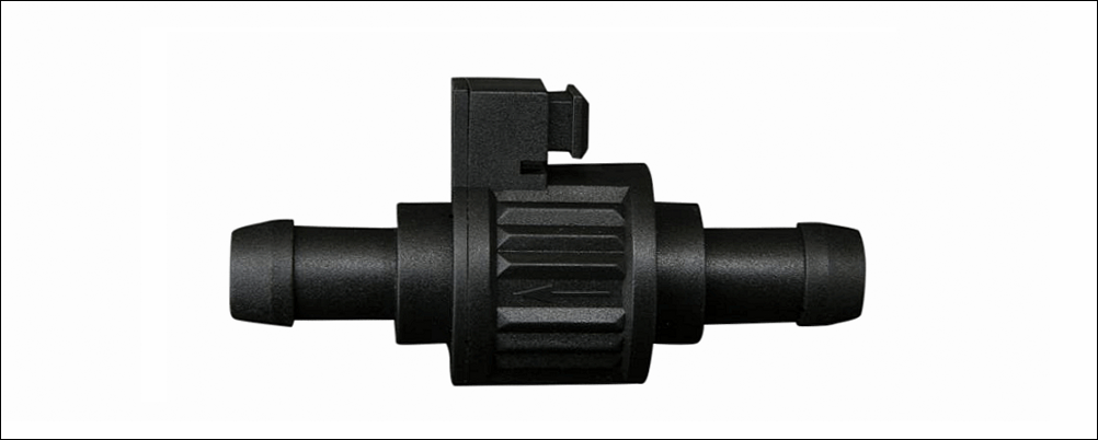
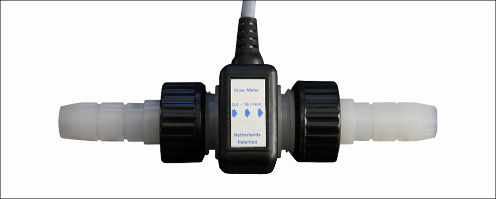
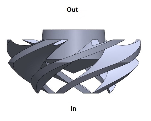
Nieuw: De 4e generatie flowmeter – Een revolutie in vloeistofmeting
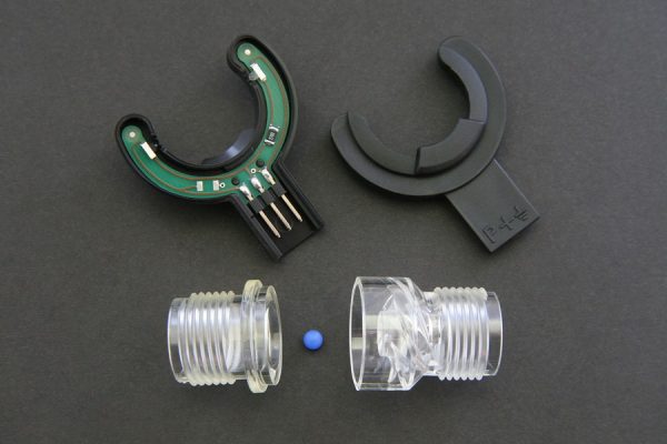
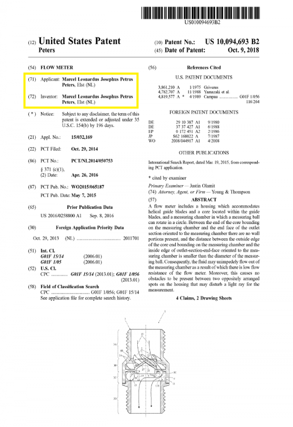
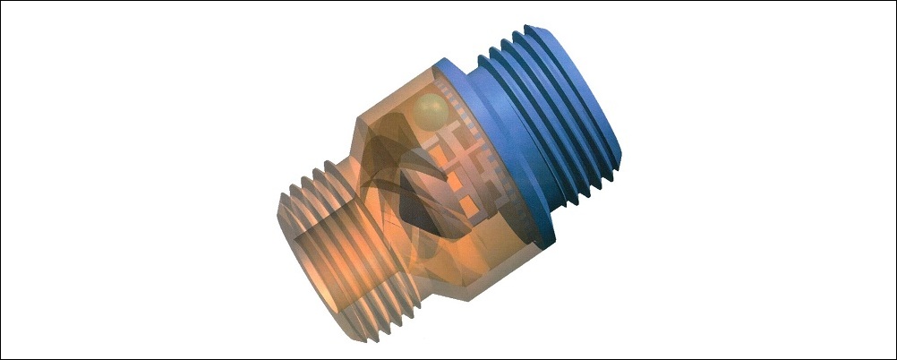
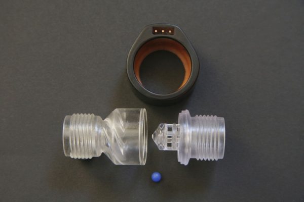
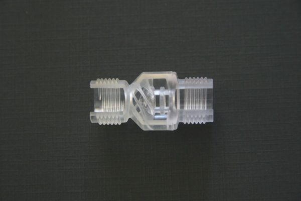
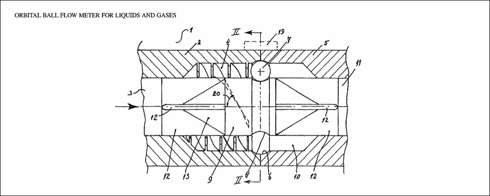
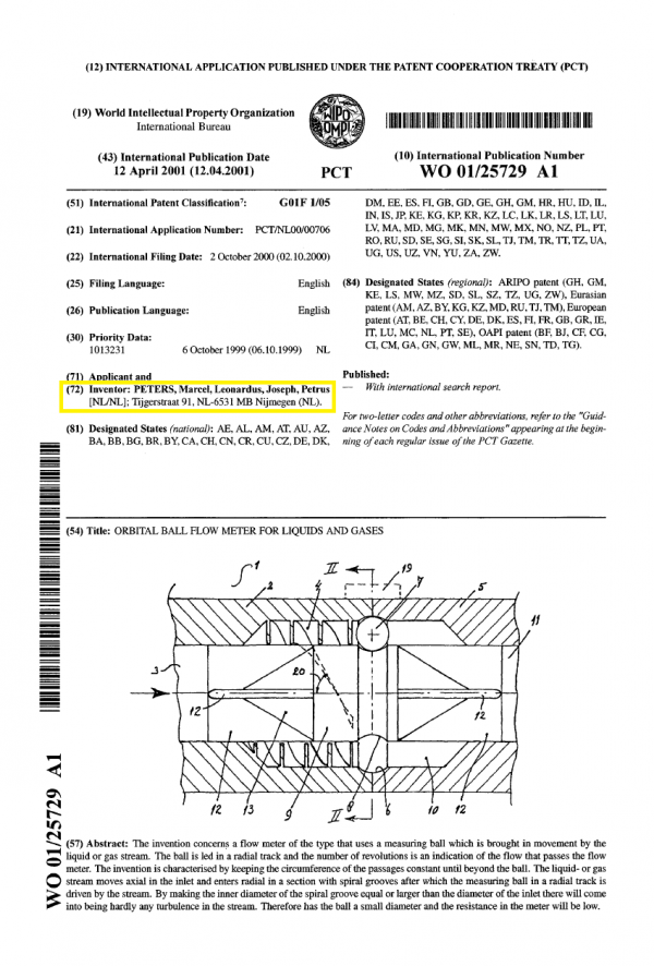
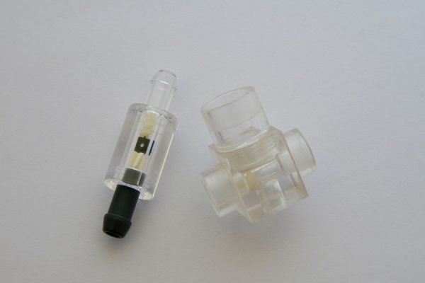
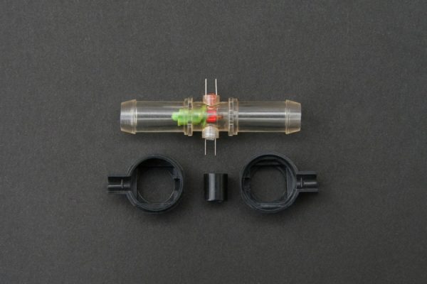
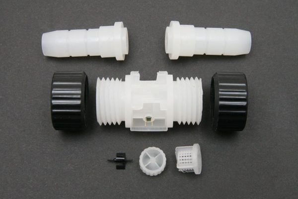
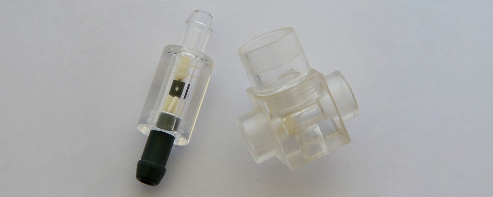
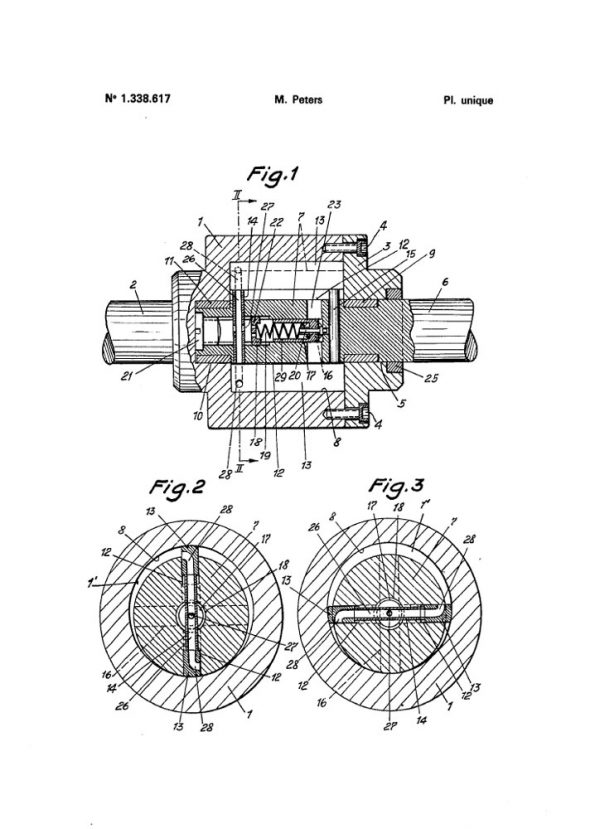
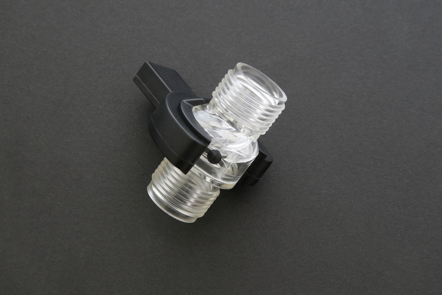
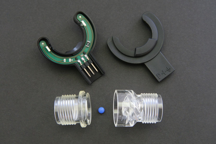
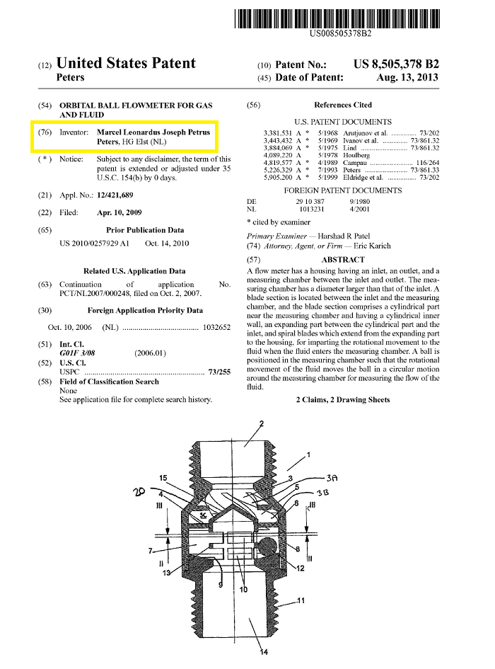
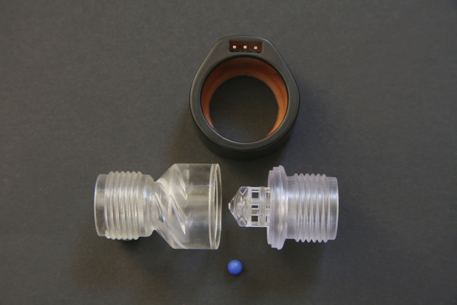
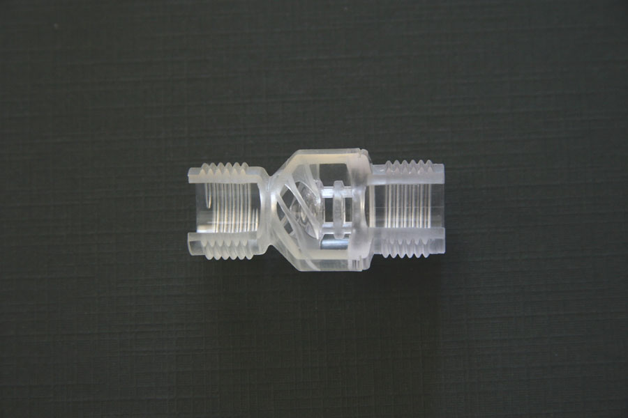
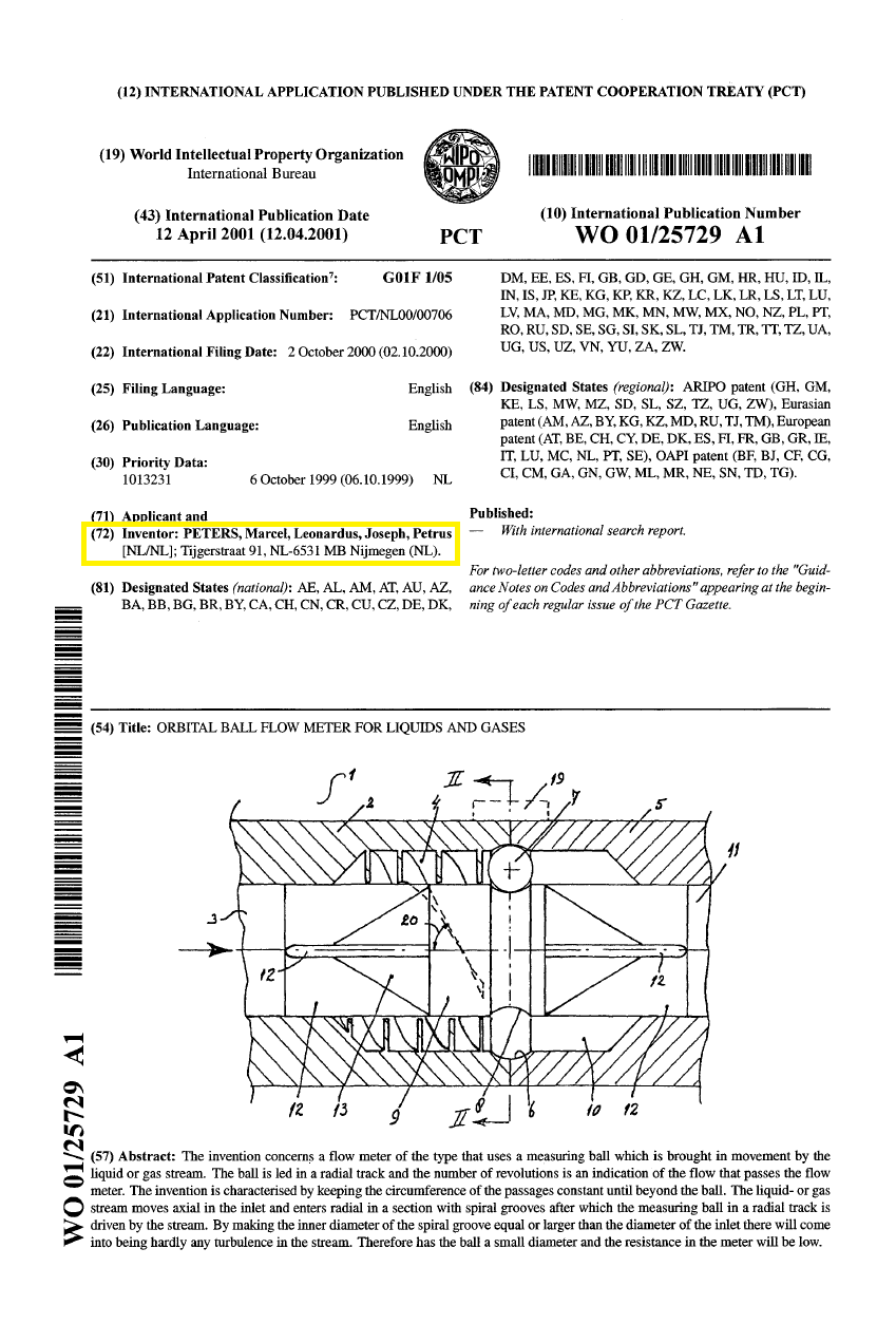
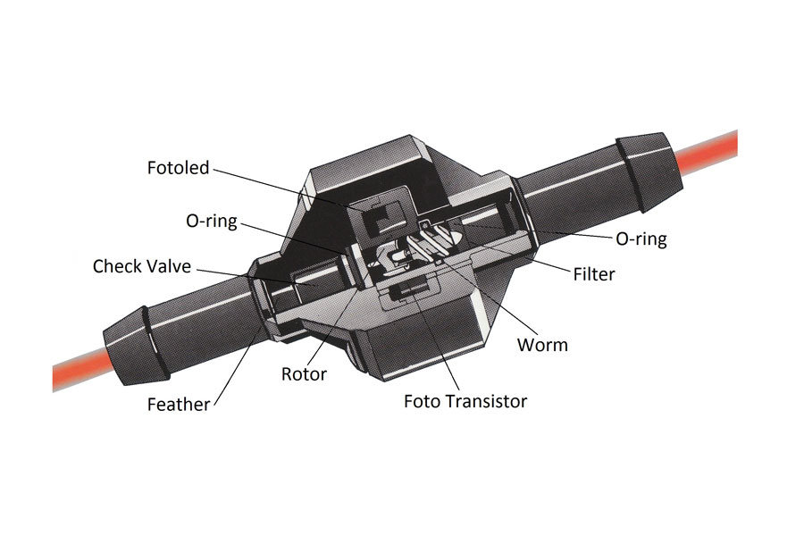
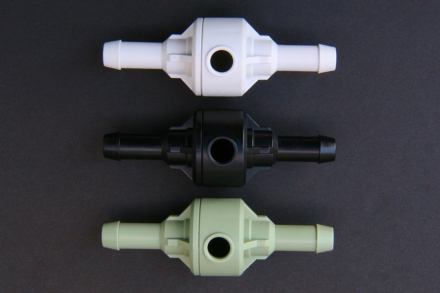
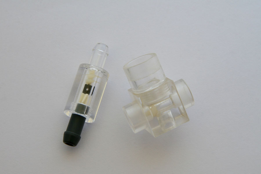
Waar conventionele flowmeters stagneren bij vervuilde vloeistoffen, gaat de 4e generatie flowmeter van PetersInvent verder. Wij hebben een baanbrekende constructie ontwikkeld waarbij een vrij roterend element (bal-technologie) de kern van de meting vormt. Dit combineert uiterste precisie met de robuustheid die nodig is voor het meten van vervuilde vloeistoffen.

Bekijk de technologie in actie:
Ontdek in enkele minuten hoe PetersInvent de markt voor vloeistofmeting transformeert. Video YouTube (2:22 min).

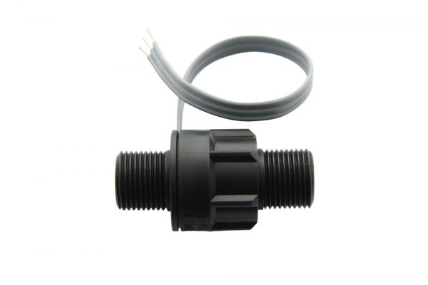
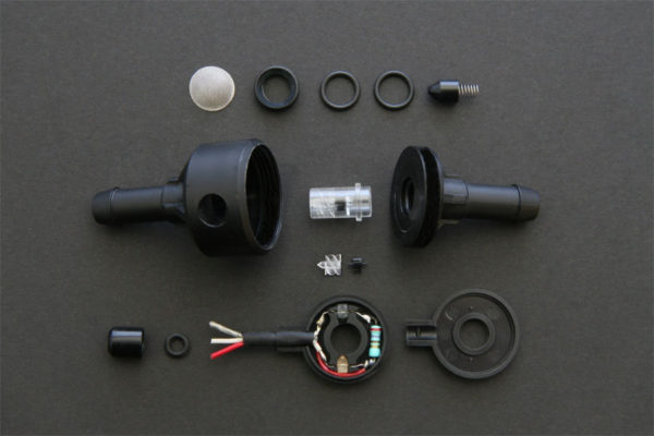
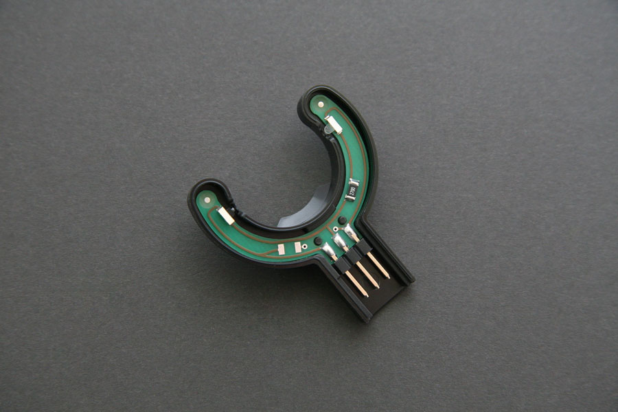
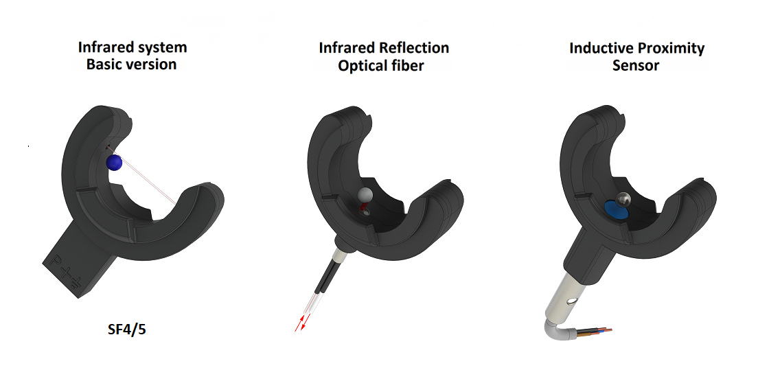
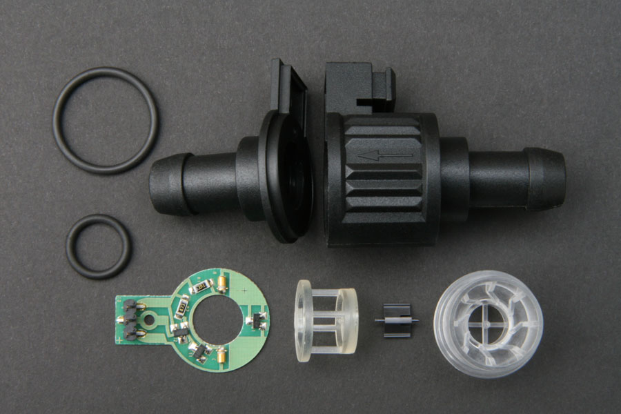
Nieuw: De 8e generatie flowmeter Rotor-serie – Ongeëvenaarde nauwkeurigheid 
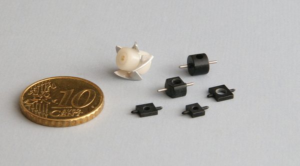
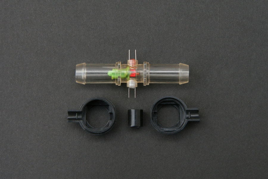
De inmiddels 30 jaar oude 2e generatie flowmeter heeft een metamorfose ondergaan. Dankzij innovatieve toepassingen is voor het eerst volledige massaproductie mogelijk, waarbij er aan de montagetechniek geen mensenhand meer te pas komt. Deze 8e generatie flowmeter is het resultaat van 25 jaar expertise op dit specialistische gebied en is zo efficiënt ontworpen dat deze tegen een zeer scherp ‘low budget’ tarief geproduceerd kan worden, zonder in te leveren op kwaliteit. Sterker nog: de nauwkeurigheid is door de nieuwste ontwikkelingen zelfs verbeterd.

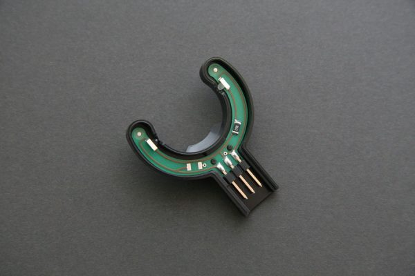
Ook de elektronica is volledig vernieuwd en wordt nu volledig geautomatiseerd en kostenefficiënt samengesteld. Onze eerste drie generaties rotor-flowmeters zijn al ruim 30 jaar de benchmark voor het doseren van hoogwaardige, schone vloeistoffen. Dankzij een ultralichte rotor van slechts 0,0047 gram bereiken we een meetnauwkeurigheid die uniek is in de markt.

Bekijk de technologie in actie: Video YouTube.

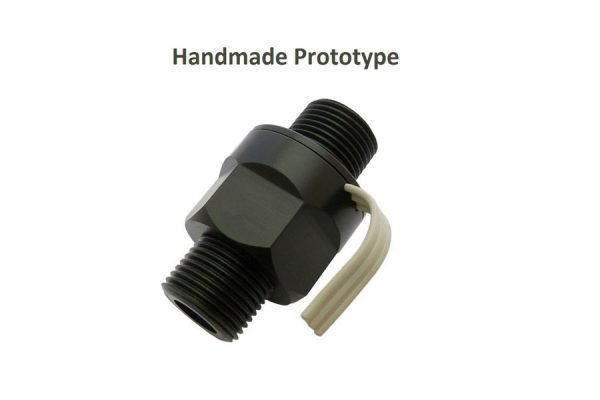
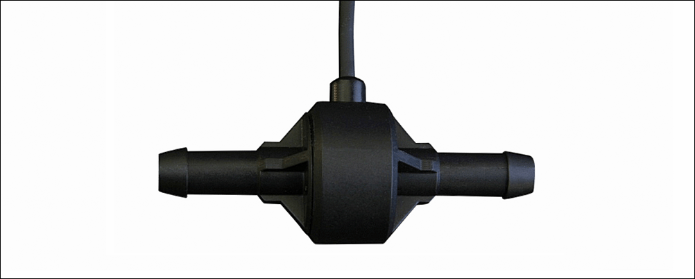
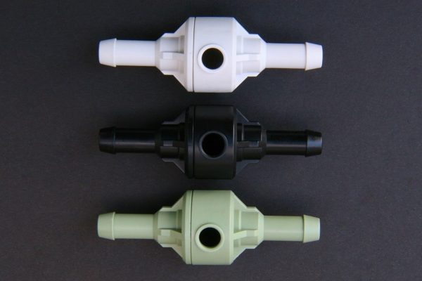
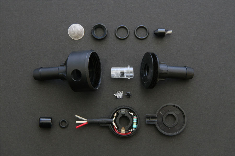
Nieuw: De 9e generatie Micrometers – Doseren met ongekende precisie
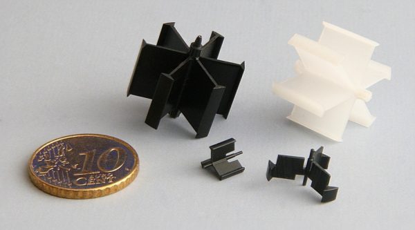
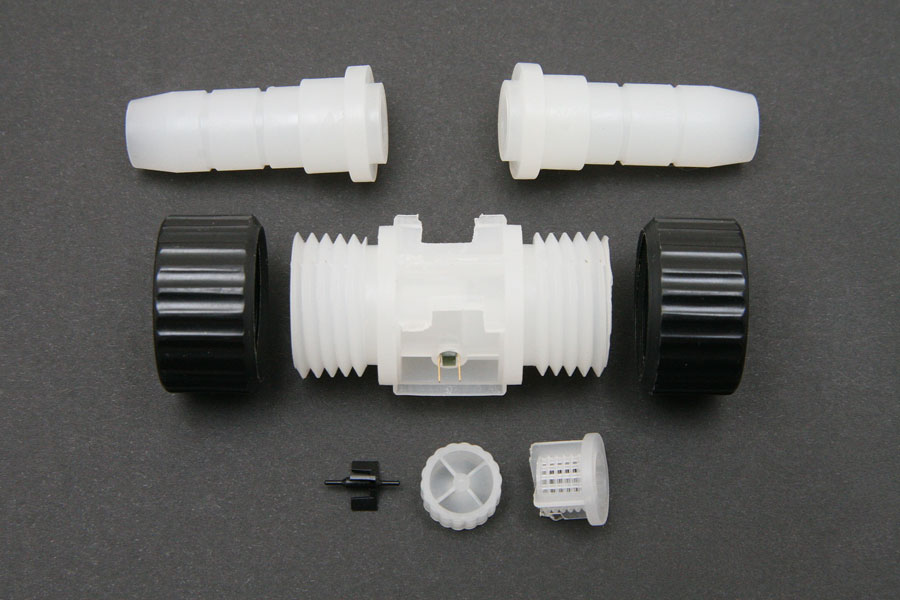
PetersInvent introduceert de 9e generatie Micrometers, specifiek ontwikkeld voor vloeistofdoseringen vanaf 0,1 ml. Deze uiterste nauwkeurigheid is cruciaal voor de farmaceutische, medische en chemische industrie. Waar elke druppel telt.

Technische perfectie in elk detail:

Milliseconde-injectie: Een geavanceerd systeem voor razendsnelle en uiterst nauwkeurige injecties.
Revolutionaire rotor: Dankzij een wrijvingsloze rotor van slechts 0,0047 gram worden doorstromingen vanaf 6 ml/min feilloos gemeten.
Maximale flexibiliteit: Keuze uit drie modellen met verschillende meetbereiken en weerstandskarakteristieken voor elke specifieke toepassing.
Betrouwbaar: Gegarandeerde precisie, zelfs bij pulserende of onregelmatige vloeistofstromen.

Bekijk de technologie in actie: Video YouTube.

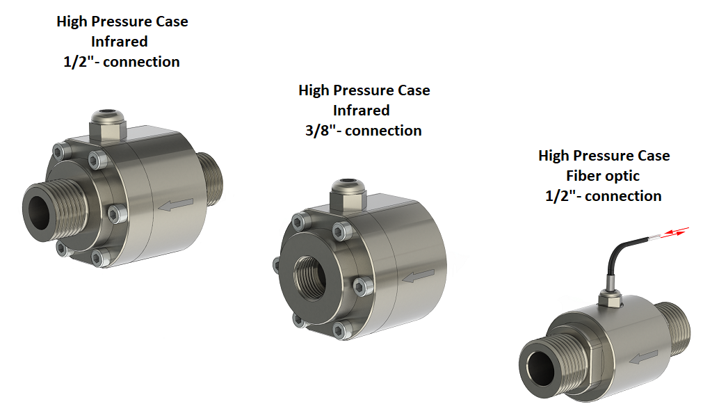
Een totaaloplossing voor elk inzetgebied
Gezamenlijk bestrijken deze drie type flowmeters een zeer groot inzetgebied. Door de stap naar volledige machinale assemblage combineert PetersInvent revolutionaire techniek met de voordelen van massaproductie. Het resultaat? Hoogwaardige doseerprecisie tegen een ongekend laag prijsniveau.

PetersInvent: De nieuwe standaard in doseringstechnologie.

Third version Fourth generation Flow Meter

WO2015065187 (A1) 2015-05-07 Inventor MLJP Peters

Uploading a video of this flow meter on knop suddenly generated a lot of interest in this innovation. Because of this video, I received a lot of response from interested companies around the world. Companies I could never have reached otherwise. Judging by the many applications, there appears to be a high demand for a flow meter with these renewed properties.

The many comments on YouTube prompted me to develop and improve the second version by making new adjustments. One of the big differences is that the 3rd version flow meter does not have a cage construction.

Info Patents
Advantages 4th generation Flow Meter
  • Due to its new construction, this flow meter is not sensitive to contaminated liquids. The gap between the blades determines the size of the dirt particles that are allowed to pass.
  • A distinctive feature of the measuring instrument is its high measuring accuracy in a variable range between 1 and 18 lmin with a less than 2% deviation. Repeat accuracy is less than 0.5% in this area.
  • This construction allows the liquid or the gas to flow in two directions without problems. The infrared measurement is in one direction, the direction in which the fluid is swirled by the worm and the ball is rotated by the swirl.
  • The flow meter can be mounted in any desired position. It is not sensitive to air bubbles in the conduit. Best position is vertical, the flow going upwards. This applies to all flow meters. Gravity causes the air bubbles to be naturally carried along with the flow.
  • The new construction allows for quick and easy assembly. The assembly can be done automatically. Due to this new development, the flow meter is very suitable as a mass-produced item for a variety of applications.
  • Because of this construction it should be possible to dose thicker fluids, like paint or gear oil SAE150 with Viscosity 43.000 CentiStokes. The temperature of the oil and the throughput speed are important.
  • Due to the construction of this flow meter, it is possible to adapt the specific gravity of the ball (plastic/metal) to the different types of fluids. The weight of the ball can be adjusted to the fluid viscosity for the best results.
  • By installing a metal housing, this flow meter can operate at a pressure of 100 bar or more.
  • Because of the open worm and open outlet, there is less pressure drop compared to other flow meters. The fluid flow is minimally impeded at the outlet of the flow meter.
  • Thanks to its advanced construction, the flow meter is easy to clean. If the flow meter is blocked by dirt particles that are too large for the flow meter to handle, the dirt/blockage can easily be removed by letting clean liquid flow through the flow meter in the opposite direction.
  • The flow meter is small and compact, making it easy to install.
  • The electronics that detect the bullet can be converted into three different systems: Infrared System, Infrared Reflection System, Inductive Proximity Sensor. This makes the flow meter even more widely applicable. The Infrared System is the most common and also the most inexpensive system.
  • Because of the infrared reflection system, the flow meter can be completely immersed in the liquid. Together with a metal housing, the flow meter is also suitable for explosive fluids.
  • With the Inductive Proximity Sensor, a metal ball can be detected in non-transparent liquids, such as paint, milk, oil or high viscosity liquids.
  • This latest ball-based flow meter is very suitable for pressurized liquids and liquids with gas bubbles, such as carbon dioxide in beer. This is a problem with plastic flow meters equipped with a rotor: whenever a gas bubble passes the rotor, due to the pressure in the pipeline, shortly rotates the rotor so fast that the shafts of the rotor may fuse into the bearings. This means that flow  meters with a rotor are less suitable for systems like this.
Advantages 360° click system electronic housing
  • The plastic housing for the electronics can be placed in desired position as a 360º click system, unlike the cumbersome assembly between the pipes, as is required for flow meters with a fixed electronic connection.
  • The electronics housing can be turned 360º around the flow meter while the latter is in operation. The plug can be easily removed and fits in only one way.
  • The electronics housing can be clicked on or removed from the flow meter while it is running. Due to this construction there is no contact with the liquid, allowing these operations to be done in a sterile way.
  • The rotation of the ball is visible through the opening of the electronics housing, making it possible to easily find the cause of a malfunction.
  • For disposable systems in which only the flow meter is replaced, the electronics can be used over and over again. Because the electronics and flow meter are independent components, the flow meter and electronics are available separately. Reuse of the electronics is not only cost-effective but also environmentally friendly.
Second version Fourth generation Flow Meter
Silver medal at the International Trade Fair iENA at Nürenberg, 2 November 2013, with the Highly Accurte,
Low Cost, Disposable Flow Meter.
Inventor MLJP Peters
Info Patents
First version Fourth generation Flow Meter

NL1013231 (C2) 2001-04-09 Inventor MLJP Peters

The fourth generation flow meter is constructed in a completely different way. We succeeded in constructing a very accurate flow meter that is no longer susceptible to contaminated liquids. This greatly increases the applicability of the flow meter.

Due to this new construction, the assembly time is considerably shortened to just a few seconds. Because of its simplicity, the assembly can be fully automated to produce large numbers.

The rotor has been replaced by a ball. The first test results are amazing, as seen on knop at 3.40 minutes in which a pipeline full of sand flows through the flow meter smoothly and completely.

When the sand has passed the flow meter, the ball continues to rotate without problems. This is possible due to the new ball-based construction. This test is heavily exaggerated, but the results are amazing.

After some time I came up with new ideas to improve the first version of the fourth generation flow meter. This resulted in the second patent application of the fourth generation: a new constructed ball-based flow meter.

Technical developments will never stop. This also applies to flow meters. Inventors will always strive for continuous innovation. When the product has been brought to market, new ideas will be developed. The possibilities of the fourth generation flow meter are an example of this.

Info Patents
Third generation Flow Meter

In 1990, P.J. Peters develop the third generation Flow Meter.
On 16-11-1990 a European patent was filed. The European patent was granted on 29-6-1994, Publication No. 0 485 684 A1. Inventor P.J. Peters.

The first and second generation flow meters have a housing, rotor and a worm. Those three components form the heart of the flow meter.
The housing contains a narrow bridge with a bearing hole in the middle. First, the rotor is positioned in the bearing hole of the housing part. At the end of the worm there is another bearing hole. Finally the worm is carefully pushed into the housing part. At the same time, the rotor shaft should be positioned in the bearing hole of the worm. The assembly is a very precise job. In the third generation flow meter, the housing and flow guides form one piece. The flow guides are not spiral shaped like in the first and second generation flow meters, but straight with an angled tip. This generation also requires the rotor to be mounted manually. The rotor and the shafts are inserted in a bearing hole of the housing and into a bearing hole of the stop plate. The bearing hole is in the middle of the stop plate. The round stop plate that is clamped into the housing of the worm will force the fluid to flow into the flow guides at the last moment, causing the fluid to swirl.

For the first time, we used a PCB on which the photocells and other components were automatically mounted with a pick-and-place system.
The assembly of the rotor is still a precise and time-consuming job in the third generation flow meter.
The first three generations of flow meters with a rotor are not suitable for mass production, as their difficult assembly must be done manually.

Second generation Flow Meter

In 1984, P.J. Peters develop the second generation Flow Meter.
The big difference between the 1st generation and 2nd generation flow meter is the design of the rotor blades and housing of the electronics. The three blades of the 2nd generation rotor are curved, allowing for a more effective contact with the fluid. The housing for the photo cells is constructed differently than in the first generation flow meter. Due to the super-light construction of the rotor 0.005 gram, which has a peak frequency of maximum 81.800 rotations per minute at 4 L/min. The fluid can be measured and dosed very accurately.

First, the Swiss patent was requested on 12-12-1985. The patent was granted on 15-02-1989, No. CH 669 039 A5.
The European patent was granted on 15-07-1987, Publication No. 0 228 577 A1
The U.S. patent was granted on 29-03-1988, No. 4,733,570. Inventor P.J. Peters

First generation Flow Meter

In 1978, P.J. Peters develop the first generation Flow Meter.

The Dutch patent was filed on 21-12-1979 under No. 7909271, and was granted on 10-06-1980, patent no. NL 8003374.
The European patent was granted on 09-04-1986, Publication No. 0 031 629 A1
The U.S. Patent was assigned on 02-08-1983, No. 4,395,919. Inventor P.J. Peters

The flat rotor of the 1st generation flow meter shows a “lagging effect”. Later, a rotor was developed with three straight blades. The first rotor blade now has three openings instead of one.
These openings cause an interruption of the infrared signal while rotating, generating three pulses per rotation. The new construction of the rotor weighs 0.004 grams. Whith a peak frequency of 24.000 rotations at 2 L/min per minute. the fluid can be measured and dosed very accurately.

Development Rotors

Development different versions rotors in the period between 1978 to 1990.

Introduction first development Flow Meter

In 1978, P.J. Peters came up with the idea of developing an accurate fuel flow meter for cars. This innovation was prompted by the oil crisis and ‘car-free Sundays’ in the Netherlands and Belgium from November 1973 to January 1974.

From 1978 to 1979, P.J. Peters invented his first working Flow Meter.
At the end of 1997, a prototype flow meter was developed to accurately indicate the fuel consumption of vehicles every second. This flow meter was primarily intended to register the gasoline consumption in cars. By directly confronting the diver with their driving style, they are able to adjust their driving style to their gasoline consumption. This allows cars and lorries to become more than 12% more fuel efficient. Drivers will immediately see when they are driving most efficiently by applying more or less throttle or changing gears at the right time. All fuel first flows through the flow meter. The mechanically constructed flow meter continuously measures the fuel consumption. It cannot be cheated with.

Whether it is cold or hot, driving uphill or downhill, short or long drives, the actual fuel consumption is continuously recorded by the flow meter.

Due to the light construction of the rotor 0.004 grams, which has a peak frequency of maximum 36.900 rotations per minute at 2 L/min. the fluid can be measured and dosed very accurately. In the housing, the fluid (liquid or gas) is swirled. The rotor in the housing is rotated by the swirled fluid. By counting the number of rotations, a reading can be obtained, which is representative of the amount of fluid that flowed through the meter.

This prototype was not yet ready for production. with this prototype it was possible to test in cars. Making a prototype ready for production, suitable for mass production is a completely different story. This requires specialist knowledge and innovative adjustments to achieve this in terms of production technology. Newspaper article De Gelderlander March 3, 1983; This will be a gold mine

Research has shown that the flow meter has many more useful applications. It consists of plastic parts, with some electronics for detection of the rotor.

The first three generations of rotor Flow Meters are still being sold today, after more than 35 years, for different applications around the world.

Inventions & Developments
Inventions & Developments in paid employment

Between 1963 and 1968, P.J. Peters was employed by the Catholic University of St Radboud in Nijmegen, as an instrument maker. During this period he was able to make several new successful developments and inventions, which were later taken into production.

  • An improved and more compact heart-lung machine.
    After changing and improving the American heart-lung machine, it was only one third of the original size.
  • New developments (in a team) in renal dialysis equipment.
  • New developments in eye measurement equipment.
  • New developments in peristaltic pumps.
  • The peristaltic pumps were reduced in size and modernised.
  • New developments in shutters for electron microscopes. Because of this invention, razor sharp photos could be made that were no longer deformed.
  • New invention: the clip or clamp made from a spring steel wire, which closes in parallel. The clamp was used to securely seal soft silicone hoses.
Improvements Photo Cameras

From 1963 to 1965, P.J. Peters repaired cameras for AGFA. He did this in the evenings, after his work at the Catholic University of Nijmegen. Many cameras suffered from the same defects. On those points P.J. Peters has made improvements, which were subsequently incorporated in the production line by AGFA.

In a later period P.J. Peters also repaired other brands of photo cameras.

Special Exposure Meter for a Hasselblatt Camera

From 1960 to 1961, P.J. Peters worked in Switzerland at Kern AG in Aarau. In Switzerland, they worked in a team to develop a special exposure meter for a Hasselblatt camera. This camera was sent into space with a rocket to take close-up images of the moon, which did not yet exist at that time. Nobody knew much about the lighting conditions in space. It was therefore necessary to develop an exposure meter with a very wide range. The exposure meter was meant to control the diaphragm by means of a mechanical coupling. When P.J. Peters was employed, they had already partly finished building the exposure meter. According to P.J. Peters, it was too susceptible to failure and had too many parts. P.J. Peters largely revised the whole design, which was a success.

The Ranger program was a series of unmanned space missions by the United States in the 1960s whose objective was to obtain the first close-up images of the surface of the Moon.

Development of a new Hydraulic Coupling

From 1960 to 1962, P.J. Peters worked on the development of a new hydraulic coupling. Change: The possibility to reach the highest torque in the drive shaft by means of hydraulics. On 30 May 1962, patent applications were submitted in:

Switzerland, no. 6735/62, 22-09-’62
Germany, no. P 30 215 XII/47h, 16-10-’62
France, no. 912 453, 24-09-’62
England, no. 36 225 and 03-08-’62
USA, no. 214 682.

The first patent 19-08-1963 was registered in France under number 1 338 617. Because of the high cost of patent application and prototype construction, this project had to be stopped halfway.

Info Patents